Coolant Temp Sensor Reading Low Catalog Library

Ambient air temperature sensor 2 Pin Connector Plug Wiring Harness fit
Coolant temp sensor wiring diagram. 1999 to 2016 Super Duty 1999 to 2016 Ford F250, F350, F450 and F550 Super Duty with diesel V8 and gas V8 and V10 engines.

Sensor De Temperatura Prova D'água Arduino Ntc 10k±1 R 18,00 em
Please provide a link to the 5V temperature sensor you're using. Most 5V temperature sensors are 3-wire. The 5V temperature sensor's 5V & Ground wires don't consume any I/O, only the Pin Mapped signal wire does. Does your EFI main harness have the Power Tap connector as shown in the center of this diagram? See "Wiring Harness Diagram", page 13.
3 wire coolant temperature sensor wiring diagram AsmaaAkasha
The 2-wire RTD configuration is the simplest among the RTD circuit designs. In this serial configuration, a single lead wire connects each end of the RTD element to the monitoring device.

2 Wire Temp Sensor Coolant Temperature Sensor Wiring Diagram
In the enchanting realm of automobile mechanics, the 2 wire temp sensor coolant temperature sensor wiring diagram reigns supreme. Its intricate patterns and mesmerizing connections depict the harmonious dance between the sensor and the engine, making it a vital piece of automotive lore. As we unravel its secrets, a neutral tone accompanies us, allowing us to appreciate the elegance of this.
.jpg)
Inside a Car Coolant Temperature Sensors
2 wire temperature sensor system January 3, 2014, 6:45pm 1 Hi everyone, I'm trying to figure out how to interact with a basic (?) 2 wire temperature sensor from an alarm clock. I still have to take it out, i was trying to figure out a way to pull it out without cutting the wires and keep the little plug but i think i'm going to have to do so.
[DIAGRAM] 1992 Chevy Truck Knock Sensor Wiring Diagram
Two-Wire Temperature Sensor The Type LM35 temperature sensor from National Semiconductor is very popular for two reasons: it produces an output voltage that is directly proportional to the measured temperature in degrees Celsius, and it enables temperatures below zero to be measured.

[DIAGRAM] 6 Wire Wiring Diagram Free Download
By Lambda Geeks The wired temperature sensor is a device used to measure and monitor temperature in various applications. It is designed to be connected to a wired network or system, allowing for real-time temperature readings and data transmission.

vdo tachometer wiring diagram
* Oil pressure sensor - Generic brand with 3 wires (Grnd, 5v & signal) * Water temp sensor - AEM Water Temp Sensor - 30-2012 (Grnd, 5v) * Boost solenoid - AEM 30-2400 (claims it needs switched 12v and the 2nd wire claims to have to go to the AEM EMS's PW2 output.whatever that is)
Up Battery Wiring Diagram Two Complete Wiring Schemas
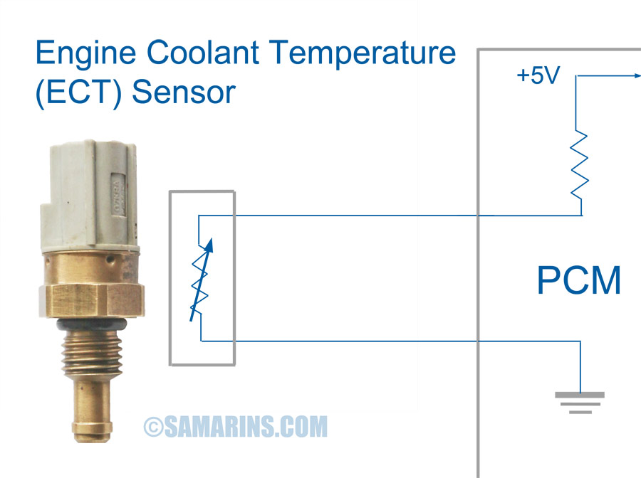
Types of Coolant Temperature Sensors There are three types of coolant temperature sensors: 1-wire, 2-wire, and 3-wire sensors. Each type of sensor has a different wiring diagram and is used in different engine control systems. 1-wire coolant temperature sensor

3 wire oil pressure sensor wiring diagram Wiring Diagram
I have tested a popular GM coolant sensor, part #12146312 with my Uno and tested it on the bench. This sensor mounts using 3/8 pipe and has a 2-wire connector. The datasheet is here and lists the mating connector: I thought I'd share the info if anyone in the future wants to use this sensor. I started with a basic temperature sketch I found.
Installing oil temperature gauge out of Ram SRT10 Dodge SRT Forum
In the whimsical world of electrical systems, the 2 wire temp sensor wiring diagram shines like a guiding star. With its enchanting lines and magical connections, it unravels the mysteries of temperature sensing. This humble diagram unveils the secrets of how two wires work in perfect harmony to measure and transmit temperatures, awakening our inner curiosity and leaving us spellbound.
TwoWire Temperature Sensor Circuit Diagram
A 2 wire temp sensor wiring diagram is a great way to ensure the accuracy of your temperature readings. It's easy to use and can help you identify any potential wiring problems before they become a problem. So, if you need to install a thermistor in your wiring project, make sure you use a 2 wire temp sensor wiring diagram.
2 wire temp sensor coolant temperature sensor wiring diagram
A 2-wire sensor of course only has 2 wires including a power wire and ground wire with connection options of Polarized and Non-Polarized. A Polarized option requires the power wire to be connected to the positive (+) side and the ground wire to be connected to the negative side (-) of the power supply.
Wiring Diagram For Temp Gauge Wiring Diagram Schemas
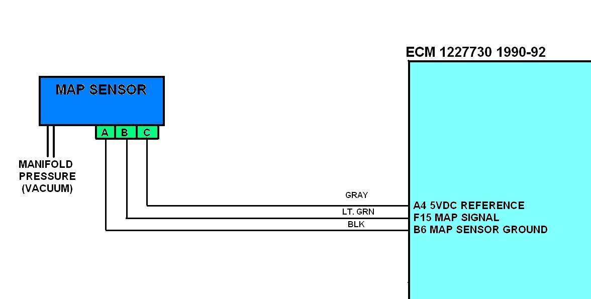
The diagram below shows the typical wiring for these sensors. ¶ Notes. Use of 2 wire temperature sensors is highly recommended. Whilst 1 wire sensors will work, they are almost always considerably less accurate. Running a dedicated ground wire back to the ECU from the sensor is also recomended. The external MAP sensor in the above diagram is.

Denso 4 Wire O2 Sensor Wiring Diagram Wiring Diagram Schematic
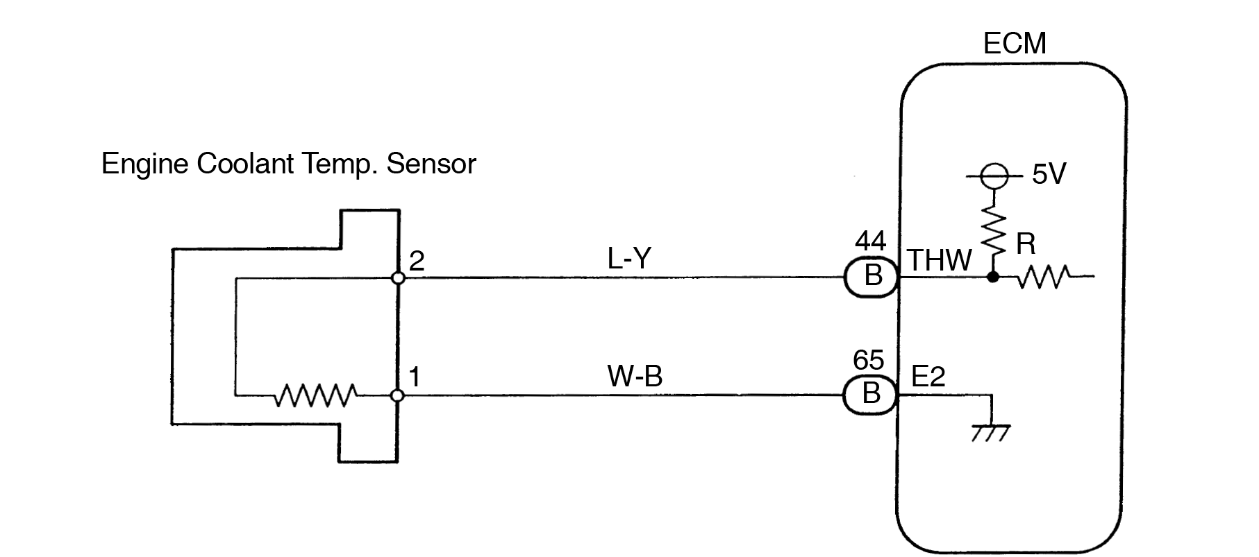
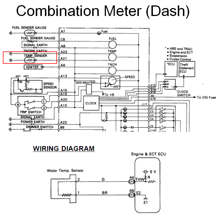
A 2-wire coolant temperature sensor consists of a signal wire and a ground wire. The signal wire sends temperature data to the ECU. Here is a simplified wiring diagram for a 2-wire coolant temperature sensor: Signal Wire ------ ECU | |-------- Ground Wiring Diagram for 3-Wire Coolant Temperature Sensor
Wiring A Temp Gauge
#1 aftermarket coolant temp sensors: 1wire vs 2 wire help. 07-27-2015, 03:00 PM got a single wire sensor on the left and a dual wire sensor on the right. Single wire sensor is for an aftermarket temp gauge, dual wire sensor is for an aftermarket fan controller.
